Drag Reduction of Wind Turbine Blade to Enhance Aerodynamic Performance: A CFD Study
Kanches Sharma1 and Priyanka Bisht2,*
1Department of Mechanical Engineering, SCE, Deharadun, India
2FE Analyst, Dresden, Germany
E-mail: Priyanka.Bisht771@gmail.com
*Corresponding Author
Received 02 February 2022; Accepted 03 April 2022; Publication 04 March 2023
Abstract
The focus of the current majority of research efforts are focused on the investigation of passive flow control systems to provide wind turbine makers with efficient tools to increase the amount of energy that a wind turbine can use. In the current effort, our goal was to find a solution to enhance the HAWT blade aerofoil’s aerodynamic performance. Due to the ease of access to wind resources, wind energy is seen as one of the most significant energy alternatives for the future. From this, we may infer that multidisciplinary and necessary study in this area is required. This study aims to boost the operating capacity of wind turbines and their overall performance by performing full or partial flow attachment. The current work is focused on analyzing the flow around a wind turbine blade using CFD analysis. The current focus is on applying passive flow separation management to increase the aerodynamic efficiency of HAWT blades with S820 aerofoils.
Keywords: CFD, Wind turbine, flow separation control methods, aerofoil, drag and lift.
1 Introduction
The primary purpose of this study is to determine the approach that has the most potential for flow control. method for wind turbine blades with a horizontal axis. For the design and study of turbine blades, the S820 aerofoil is employed. Utilizing ANSYS Fluent 15, an aerofoil’s CFD research is carried out. To investigate the flow around the blades of a wind turbine, CFD analysis is performed. In this research, our goal was to investigate ways to improve blade performance. It has been demonstrated that doing so will improve the wind turbine’s aerodynamics. The lift and the drag ratio and the lift coefficient are the two most important variables that are determined in this section so that an efficacy analysis can be carried out. of an aerofoil. The flow near to the surface is reversed as a result of the effects of viscous forces mixed with the effects of a negative pressure gradient, which separates the flow from the surface.
A significant issue in the study of fluid mechanics is flow separation. Numerous strategies were developed by researchers to solve this. Any process where a fluid flow’s boundary layer is involved responds differently when the flow develops naturally along a smooth surface. Methods of flow control to delay transitions, reduce drag, postpone separation, improve lift, etc. The goal of controlling boundary layer flow separation on an aerofoil is to maximize lift coefficient and minimize drag coefficient. The two types of boundary layer controls are passive flow control and active flow control, which both need the use of external energy.
Sharp V-grooved riblets are used in big wind turbines to reduce drag caused by skin friction. In this article, Leonardo P. Chamorro, Roger Arndt, and Fotis Sotiropoulos attempt to investigate the effectiveness of riblets as a method of reducing drag on wind turbine blades.
The behavior of riblets and the investigation of the turbulence-lent flow interaction close to the wall region were both investigated experimentally. This study used wind tunnel tests to determine how employing V-groove riblet structures may reduce drag on a wind turbine aerofoil. In this study, studies in a wind tunnel were conducted to determine the drag in a blade aerofoil employing V-groove riblets. To understand the actual situation, a comparison between the CFD findings and the laboratory tests is done.
Flow Separation Control Numerical Study over a NACA2415 Aerofoil. By (M. Tahar Bouzaher) In this study, the flow around a NACA2415 aerofoil is numerically simulated at an angle of 180 degrees. For the purpose of facilitating a smoother transition of the boundary layer, a rod is employed to adjust the flow separation upstream of the leading edge. The ANSYS FLUENT 13 version is used to analyze the issue. The rod moves repeatedly roduced using the dynamic mesh method. The variation in frequency from 70 to 400 Hz, and the amplitudes of 3% and 5% of the chord are being taken into consideration. The frequency that one choose to use is that it is equal to the frequency of separation. The results showed a maximum reduction of 61% and improve the flow behaviour.
They performed a numerical analysis of the turbulent flow over a NACA0012 aerofoil (U. Anand, Y. Sudhakar, R. Thileepanragu, V. T. Gopinathan, and R. Rajasekar). Analysis is being conducted from several perspectives. The CFD code FLUENT is applied so as to resolve the 3D Reynolds average Navier-Stokes equations as well as the equations of the Spalart-Allmaras turbulence model.
An array of tiny vanes connected perpendicularly above a blade’s surface of suction makes up a vortex generator. The degree to which the fluid is able to stick to the surface of the blade at high angles of attack is increased by the vortex generator. Numerical simulations are used to analyze vortex generator-based flow separation management above a NACA0012 aerofoil. The impact of vortex generators on the flow’s bulk quantities (CL and CD) is investigated, and the adjustments to the flow field are explored.
By using blowing apparatuses with either constant or pulsed jets, (Andreea BOBONEA, Mihai Leonida NICULESCU, and Corneliu BERBENTE) they conducted research on active flow control. In addition, they delay separation and mitigate detrimental effects by using high-velocity air that has been held between the gaps in the boundary layer.
Pressure differences. Even though there is a constant flow of fluid below the boundary layer, pulsed blowing transmits brief but very effective pulses. Many researchers have sought to conduct experimental studies simulations of active manipulation in two dimensions using numerical models in separated flows over aerofoils.
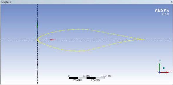
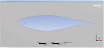
Figure 1 (S820 Aerofoil).
2 Methodology
In order A hole is bored into the leading edge side of the blade so that the flow may be separated from the top surface of the blade in a controlled manner. This hole allows a jet of air to be directed from an area of high pressure to an area of low pressure [21–25]. The border layer will receive energy as a result, delaying separation. To model the flow field around the S820 aerofoil, ANSYS Fluent 15 is applied as the CFD code. Two alternative aerofoil geometries were utilized for the analysis: an aerofoil with a slot and an aerofoil without a slot. In this study, the domain was given boundary conditions, assumptions were established, equations were used, and the findings are presented. were calculated, and the results were then compared. Aerofoil S820 with a leading edge slot and one without are two different sorts of forms in the geometry prepared for examination. Place the aerofoil 20% from the side of the leading edge. A java application is used to produce the sketch for the S820 aerofoil. This Java software was created using coordinates provided by NREL for the S820 aerofoil (National Renewable Energy Ltd.). The aerofoil was surrounded by a fluid domain that was 3000 mm long and 2500 mm wide. The geometry is produced using ANSYS design modeller.
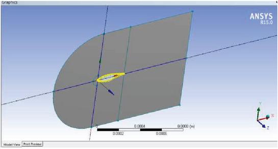
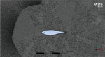
Figure 2 (S820 Aerofoil without slot).
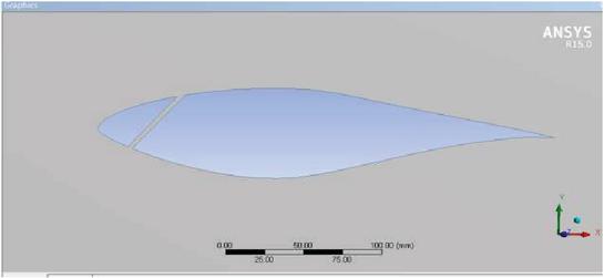
Figure 3 (S820 Aerofoil with slot).

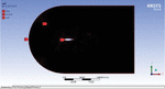
Figure 4 (Fluid domain for analysis).
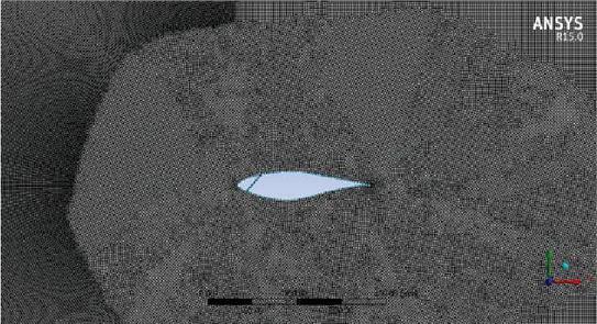
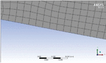
Figure 5 (Meshing of Fluid domain).
3 Mesh Details
ANSYS Fluent 15 is used for fluid domain meshing or discretization.
During meshing, the following parameters were recorded.
3000 mm is the length of the calculation domain.
The computational domain has a 2000 mm width.
250000 Nodes in total
249000 elements total.
Mesh Type: Quadrilateral
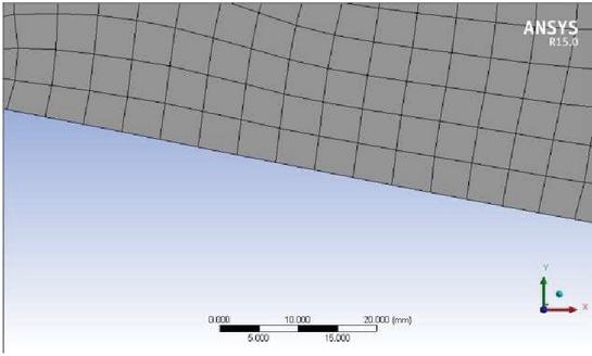
Figure 6 Quadrilateral mesh generated in ANSYS Fluent.
4 Analysis and Solution
With the following simplifying assumptions, the governing equations were solved using the commercial CFD program FLUENT:
Density-based solution for problems utilized equation: k-, SST.
Air and fluid Monitored parameters include coefficients of lift and drag.
Using the above parameter, an aerofoil is subjected to a 2D analysis. Results are acquired when analysis is conducted from several angles of attack.
5 Results and Discussion
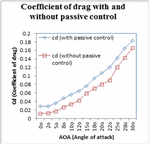
By varying the angle of attack on S820aerofoils with and without slots, analysis has been done in ANSYS 15.0 FLUENT. The leading edge slot will energise the boundary layer’s top layer and attempt to draw the flow separation towards the trailing edge.
Results from S820 aerofoils with and without leading edge slots will be contrasted in order to observe changes in drag and lift and, ultimately, an increase in aerodynamic performance. The outcomes at various angles of attack, ranging from 0 to 30.
6 Results and Discussion
By varying the angle of attack on S820 aerofoils with and without slots, During the course of the analysis, the program ANSYS 15.0 FLUENT was utilized. The leading edge slot will energise the boundary layer’s top layer and attempt to draw the a separation of flow moving toward the trailing edge.
A comparison will be made between the results of the S820 aerofoil with and without a leading edge slot in order to observe differences in drag and lift, and ultimately, an improvement in aerodynamic performance will be looked for. The findings that were obtained at a number of different angles of attack, ranging from 0 degrees to 30 degrees, are presented below.

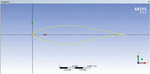
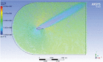
Figure 7 (Velocity vectors of S820 aerofoil with slot at AOA 30).
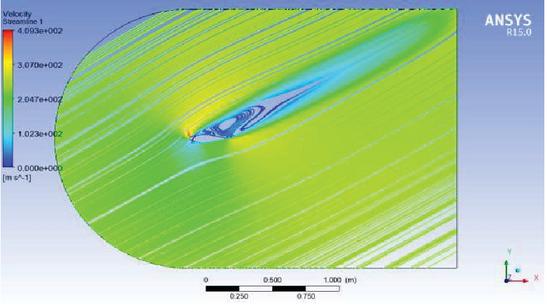
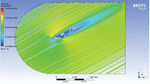
Figure 8 (Streamline of S820 aerofoil with slot at AOA 30).
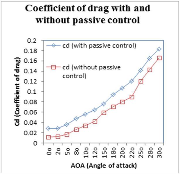
Figure 9 Coefficient of drag for aerofoil with and without passive control.
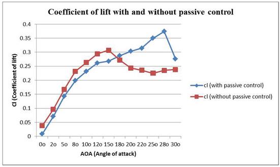
Figure 10 (Coefficient of lift for aerofoil with and without passive control).
7 Conclusion
It is essential to increase the efficacy of turbine blades in order to harness the full potential of wind energy. We need to make wind turbine blades more aerodynamic to solve the major issue of flow separation.
The flow is neatly linked to the profile by creating There is a delay in the arrival of a velocity near the boundary layer or the trailing edge of the jet.
Future wind turbine performance may be improved by using a variety of strategies, including passive flow control systems.
The study yields the following conclusions:
• The stall condition for an aerofoil without a slot occurs at 15 for the specified parameter and physics.
• A slotlessaerofoil’s maximum lift occurs at an angle of 15.
• Compared to an aerofoil without a slot, one with a slot provides more lift and less drag.
• In comparison to an aerofoil without slots, stall conditions occur at a greater angle of attack in slotted aero foils.
• A slotted aerofoil’s stall angle is 28 degrees, which indicates an increase in lift force.
References
[1] E. Akcayoz and I. H. Tuncer. Numerical investigation of flow control over an aerofoil using synthetic jets and its optimization. International Aerospace Conference, Turkey (2009).
[2] C. Jensch, K. C. Pfingsten and R. Radespiel. Numerical investigation of leading edge blowing and optimization of the slot geometry for a circulation control aerofoil, Notes on Numerical Fluid Mechanics and Multidisciplinary Design. 112 (2010) 183–190.
[3] B. Yagiz, O. Kandil and Y. V. Pehlivanoglu. Drag minimization using active and passive flow control techniques. Aerospace Science and Technology, 17 (1) (2012) 21–31.
[4] M. Goodarzi, R. Fereidouni and M. Rahim. Investigation of flow control over a NACA0012 aerofoil by suction effect on aerodynamic characteristics, Canadian Journal on Mechanical Sciences and Engineering, 3(3) (2012) 102–109.
[5] Bragg, M. B., Gregorek, G. M. Experimental study of aerofoil performance with vortex generators. 1987.
[6] Hansen, M. O. L. Aerodynamics of Wind Turbines, China Power Press, Beijing (2009).
[7] E. Akcayoz and I. H. Tuncer. Numerical Investigation of Flow Control Over an aerofoil Using Synthetic Jets and its Optimization, International Aerospace Conference, Turkey, 2009.
[8] A. T. Piperas. Investigation of Boundary layer Suction on a Wind Turbine aerofoil using CFD, Master Thesis, Technical University of Denmark, Denmark, 2010.
[9] B. Yagiz, O. Kandil and Y. V. Pehlivanoglu. Drag Minimization Using Active and Passive Flow Control Techniques, Aerospace Science and Technology, Vol. 17, pp. 21–31, 2011.
[10] Viswanath P. R., Ramesh G., Madhavan K. T. Separation control by tangential blowing inside the bubble. Exp. Fluids 29: 96–102.
[11] Ashill P. R., Fulker J. L., and Hackett K. C. A review of recent developments in flow control. Aeronautics J. 109: 205–232, 2005.
[12] Gad-el-Hak M. Modern developments in flow control. Appl. Mech. Rev. 48: 365–379, 1996.
[13] Boundary-layer and flow control (Oxford: Pergamon) vol. 1 & 2.
[14] Viswanath P. R., Sankaran L., Sagdeo P. M., Narasimha R., Prabhu A. Injection slot location for boundary layer control in shock-induced separation. 198.
[15] Viswanath P. R., Ramesh G., Madhavan K. T. Separation control by tangential blowing inside the bubble. Exp. Fluids 29: 96–102.
[16] U. Anand. Passive flow control over NACA 0012 aerofoil using vortex generator.
[17] M. Tahar Bouzaher. Numerical study of flow separation control over a NACA 2415 aerofoil.
[18] Leonardo P. Chamorro, Roger Arndt and Fotis Sotiropoulos. On the skin friction drag reduction in large wind turbines using sharp V-grooved riblets.
[19] Ya-Lei Bai, Xing-Yu Ma, Xiao Ming. Lift enhancement of aerofoil and tip flow control for wind turbine.
[20] Kianoosh Yousefi, Reza Saleh and Peyman Zahedi. Numerical study of blowing and suction slot geometry optimization on NACA 0012 aerofoil.
[21] Panwar, K., Murthy, D. S., “Analysis of thermal characteristics of the ball packed thermal regenerator”, Procedia Engineering, 127, 1118–1125.
[22] Panwar, K., Murthy, D. S., “Design and evaluation of pebble bed regenerator with small particles” Materials Today, Proceeding, 3(10), 3784–3791.
[23] Bisht, N, Gope, P, C, Panwar, K, “ Influence of crack offset distance on the interaction of multiple cracks on the same side in a rectangular plate”, Frattura ed IntegritàStrutturale” 9(32), 1–12.
[24] Panwar, K., Kesarwani, A., “Unsteady CFD Analysis of Regenerator”, International Journal of Scientific & Engineering Research, 7(12), 277–280.
[25] Singh, I., Bajpai, P. K., & Panwar, K. “Advances in Materials Engineering and Manufacturing Processes.
Biography

Priyanka Bisht has received her M.tech degree in Thermal Engineering from BTKIT Dwarahat in 2014 and B.Tech degree in Chemical Engineering from Banasthali University, Rajasthan in 2012. She has industrial experience as a FEA engineer at AHS3D engineering services Bangalore and around 5 years of experience working in academia research & teaching. Currently she is working as a freelance FEA analyst living in Dresden, Germany.
Journal of Graphic Era University, Vol. 11_1, 35–44.
doi: 10.13052/jgeu0975-1416.1113
© 2023 River Publishers