Performance Analysis of Conventional MPPT Techniques for a Solar PV System
Km Charu*, Padmanabh Thakur and Fahim Ansari
Department of Electrical Engineering, Graphic Era (Deemed to be) University, Dehradun, India
E-mail: charusharma.ee@geu.ac.in
*Corresponding Author
Received 26 December 2022; Accepted 23 January 2023; Publication 11 April 2023
Abstract
The effectiveness and accuracy of two different MPPT methods of solar photovoltaic (PV), namely Perturb & Observe (P&O) and Constant Current (CC) have been investigated in this study. The main objective of this study is to test the impacts of temperature and solar irradiance (insolation) variations on solar PV output power which are achieved through these methods. Usually, solar insolation and temperature are the two most important influencing factors that have a significant impact on the output power (Pout). Here, the two conventional MPPT techniques have been applied to analyze the response through power characteristics curves of solar PV systems subject to changing environmental conditions. The MPPT techniques have been implemented on the solar PV system using MATLAB. Additionally, the output power curves at various irradiances are shown in this work. The research demonstrates that the P&O-based MPPT method outperforms the CC-based MPPT method.
Keywords: Solar PV system, maximum power point tracking (MPPT), Perturb & Observe (P&O), constant current (CC).
1 Introduction
Due to its widespread availability and ecologically benign characteristics, solar photovoltaic (PV) generation using renewable energy is the ideal replacement for conventional energy sources. PV arrays, which typically collect electric power from solar energy [1], exhibit non-linear I-V characteristics. They also have the benefit of not requiring maintenance and being pollution-free, but they are limited by the fact that the solar cell efficiency is very low and the low efficiency of the solar PV system is a significant issue. If the weather is bad, the system’s efficiency hardly rises above 20%, and the conversion efficiency is even worse. Generally speaking, the two most important elements that influence a PV system’s efficiency are solar cell temperature and irradiation. In order to gain 20–30% more energy, the efficiency can be increased by applying the MPPT technique. The primary goal of MPPT algorithms is to decrease oscillation brought on by changing weather conditions while achieving quick and precise tracking performance. In general, a solar system’s output power is influenced by cell temperature and solar irradiation.
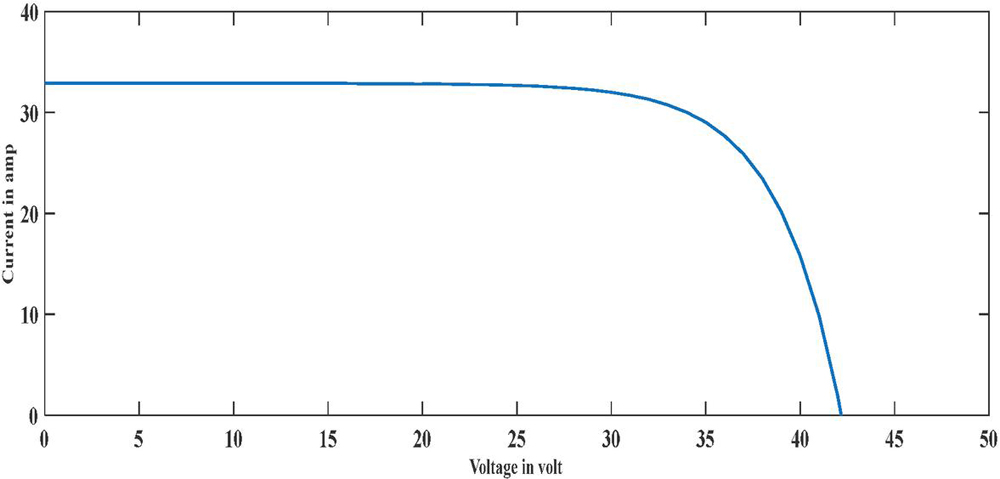
Figure 1 I-V characteristics with uniform insolation.
The characteristics of a PV array at uniform irradiation levels are shown in the Figures 1 and 2. When both parameters are altered, the output characteristics change. The P-V & I-V characteristic curves of a solar PV system are shown in Figures 3 and 4 under various irradiance conditions. Utilizing environmental conditions, MPPT aims to dynamically obtain maximum power. To increase the effectiveness of the solar PV system, a variety of MPPT approaches have been presented. Typically, this technique is classified into two categories, namely offline and online methods. Fractional open-circuit voltage (FOCV) [2–6] and fractional short circuit current (FSCC) [7–12] are offline techniques, while Perturb and Observe (P&O) [13–16] and Incremental Conductance (INC) are online techniques [17–27].
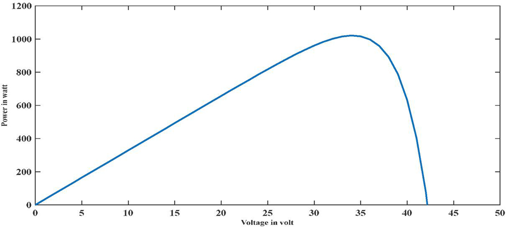
Figure 2 P-V characteristics with uniform insolation.
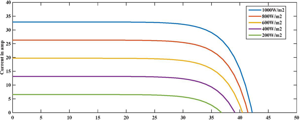
Figure 3 I-V characteristics with different insolation.
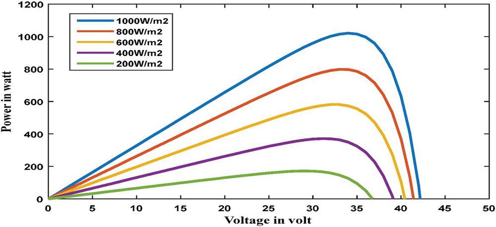
Figure 4 P-V characteristics with different insolation.
Figures 3 and 4 depict the impact of change in solar insolation on the MPP of P-V & I-V curves. The following observations can be highlighted in Figures 3 and 4:
I. Decrease in Pout with a decrease in the magnitude of insolation.
II. The P-V characteristics curve is shifting to the left with a decrease in insolation.
Similarly, the I-V characteristics curve is shifting to the left with a decrease in insolation.
It is worth mentioning at this point, that the short circuit current () of solar cells is a function of irradiance; hence it decreases in proportion to the reduction in irradiance.
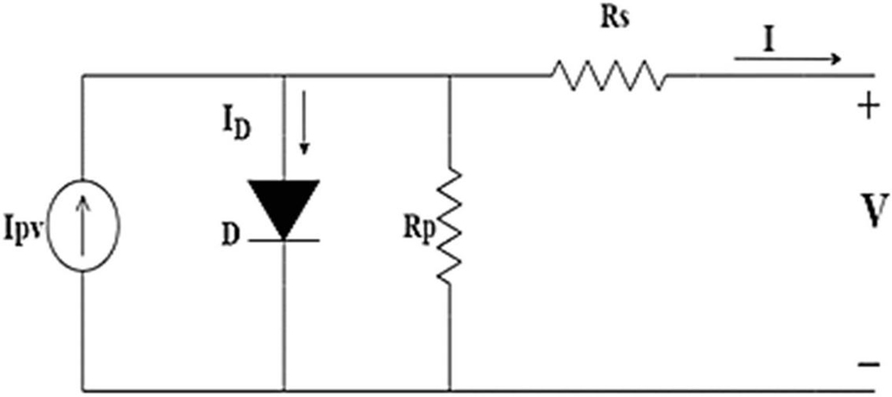
Figure 5 Single diode model.
2 Mathematical Model of Solar PV System
The basic goal of PV module modelling is to reproduce the behaviour of the PV modules. A number of panels connected in series and/or parallel combinations make up the PV array current. Figure 5 depicts the analogous circuit for the single diode model, which consists of a diode, parallel and series resistance, and resistance (D).
| (1) |
A Diode ideality factor,
Thermal voltage,
number of cells in series,
Parallel resistance,
Series resistance,
diode dark saturation current,
light-induced current,
The thermal voltage of the solar PV array is given by
| (2) |
Where;
q Electric charge,
K Boltzmann constant (i.e., 1.3806452 10 J/K,)
T Operating Temperature for PV system (in Kelvin),
Table 1 Manufacturer datasheet of solar PV module [28]
| Parameters | Values |
| Power at MPP (Pmax) | 62.006 Watt |
| Voltage under OCC () | 10.9 Volt |
| Current under SCC () | 7.82 Amp |
| Voltage at MPP (V) | 8.6 Volt |
| Current at MPP (I) | 7.21 Amp |
| No. of series cells () | 18 |
| Diode saturation current () | 3.0763 10A |
| Diode ideality factor (A) | 0.89864 |
| Series resistance () | 0.14761 |
| Parallel resistance () | 38.1127 |
| Photo generated current () | 7.8503A |
3 Constant Current (CC) Method
This method is based on the same working principle of the constant voltage method Which is fractional to short-circuit current MPPT method [29, 30]. The highest power point in this technique reaches between 78% and 92% of the short circuit current () while the PV array runs at constant current [31, 32]. Therefore, the sensed parameter is short circuit current (Equations (3) and (4)).
| (3) | ||
| (4) |
Where is the current at maximum power point and is the short circuit current of the PV system.
Figure 6 depicts the constant current method’s flowchart. Compared to the constant voltage technique, this method is more precise and effective [33]. The CC method’s fundamental flaw is that it depends on the measurement of the short circuit current value. To test the short-circuit current’s value, the module must be disconnected and short-circuited. There is a loss of power when the PV module is unplugged. This method is typically combined with other MPPT techniques since the short-circuit current fluctuates with changing weather circumstances like irradiation level. As a result, a hybrid version of the current methodology can readily track MPP under all operating situations [34].
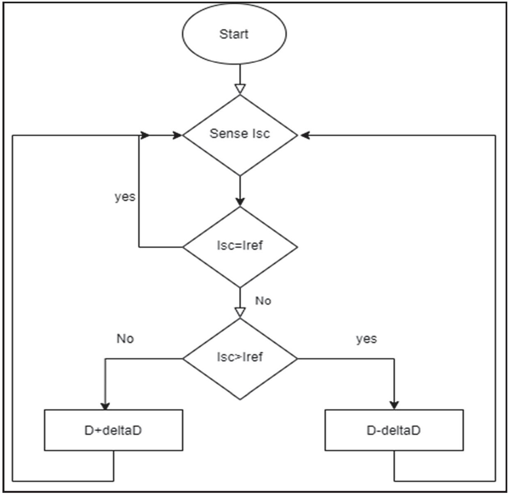
Figure 6 Flow diagram of CC method.
4 Perturb and Observe (P & O) Method
This approach measures the PV voltage and current first and then calculates the related power. Iterative methodology essentially describes this process. Because it is simple to implement, this method is used. By changing the operating voltage and monitoring the changes in power both before and after the perturbations, this method allows for the tracking of MPP. Then, based on variations in power, it produces the duty cycle perturbations. Figure 7 depicts the P&O method’s flowchart.
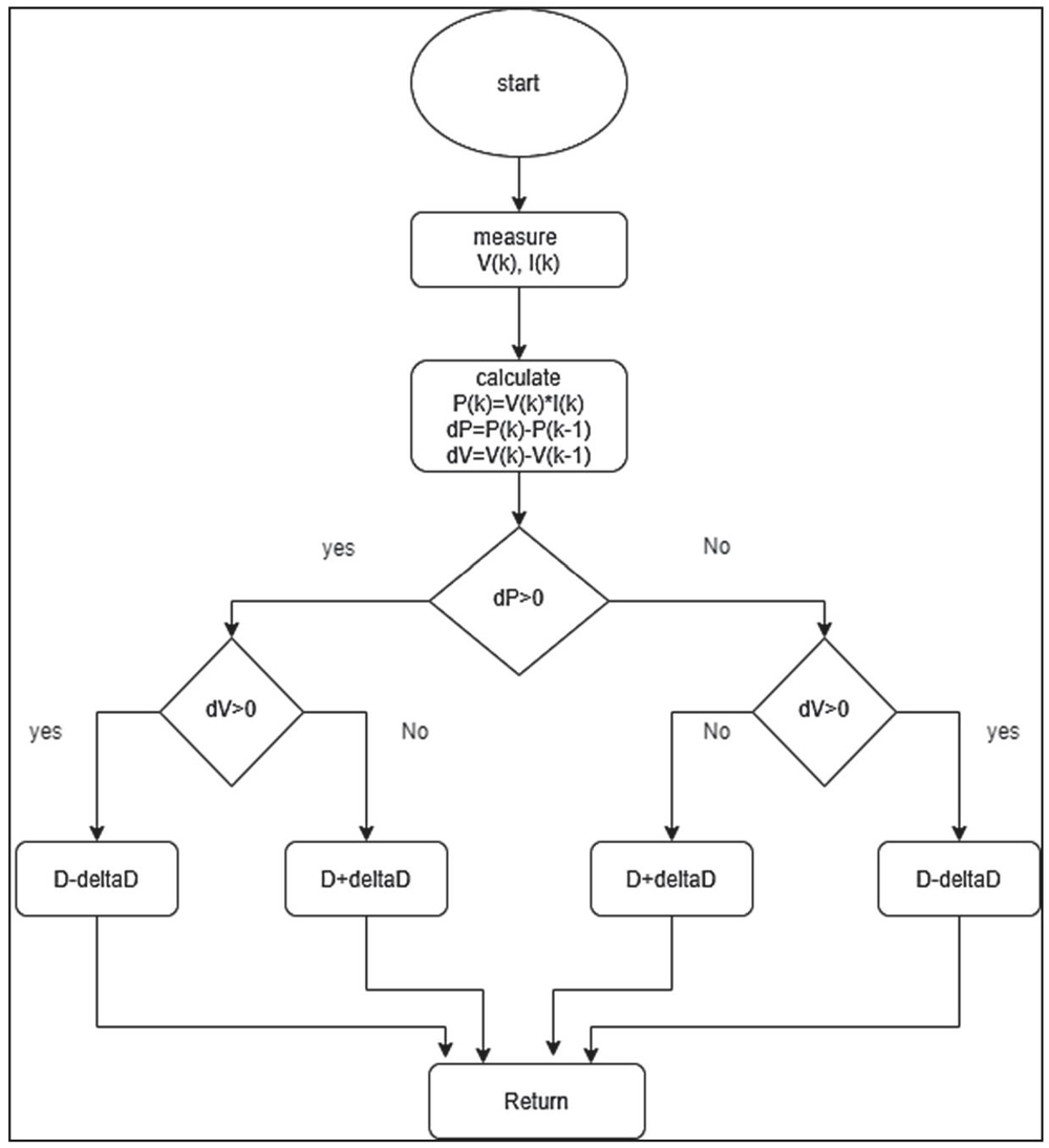
Figure 7 Flowchart of P&O method of MPPT.
If the power change to the voltage change is positive, the MPP shifts to the left; otherwise, it shifts to the right. Additionally, this process continues until () equals zero [35–38]. This method’s primary flaw is that it deviates from the maximum operating point when atmospheric conditions are quickly changing. The tracking speed and oscillation are traded off to get the perturbation magnitude in the P&O. When a minor perturbation is applied, oscillations close to the MPP are reduced with a slower tracking speed, and when a big perturbation is applied, a rapid tracking speed with more oscillations is the consequence.

Figure 8 Power Waveform obtained through Constant current method.
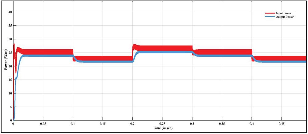
Figure 9 Power Waveform obtained through the P&O method.
5 Results and Discussion
The results are presented in this section. In Figures 8 and 9, the red waveform and blue waveform depict respectively the input power and output power. Step variations in input power correspond to changes in irradiance, and it is clear from the data that output power tracks these changes as well. In both Figures 8 and 9, the input power is the output of the PV panel used. However, the output power is the power at the output of the converter. From the analysis, it is observed that the CC technique is failed to eliminate the transients at every step change. It is also observed that CC is less efficient in tracking the input power (the response is depicted in Figure 8). On the other hand, Figure 9 depicts the response of the model through P & O technique. It is observed that the P&O technique is efficient in tracking the input power. Also, there are almost negligible transients at every step change. On comparing the results obtained through CC and P&O techniques, it is observed that the P & O technique provides better tracking and power extraction than the CC technique.
The values of input and output powers as obtained from CC and P&O techniques have been given in Table 2.
Table 2 Values of the power and percentage extraction
| Input | Output | %Age Extraction | |
| Technique | Power (W) | Power (W) | of Power |
| Constant Current (CC) | 12.86 | 12.11 | 94.17% |
| Perturb and Observe (P&O) | 23 | 21.68 | 94.26% |
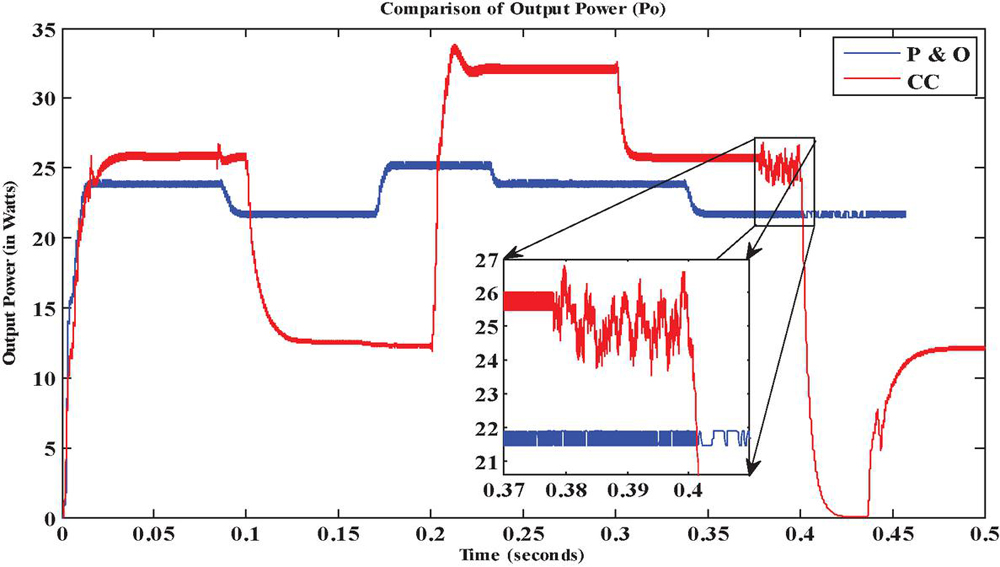
Figure 10 Comparison of the output power.
Figure 10 shows the waveforms of the output power obtained using both techniques (red waveform – CC technique and blue waveform – P & O technique). The zoomed part in Figure 10 shows the presence of transient in the output. The waveforms also depict that at every step change, CC technique exhibits transient which are major between 0.35 s to 0.4 s (as shown in the box in Figure 10). However, the P&O technique gives almost a smooth output with almost negligible transients. This comparison shows that the MPP tracking produced by the P & O technique is better and has fewer transients than that produced by the CC method.
6 Conclusion
The performance of the CC technique (also known as the Fractional Short Circuit Current (FSCC) technique) and the P & O technique, two well-known conventional MPPT procedures, has been briefly studied in this research. The P & O methodology of MPPT is an online technique, whereas the CC technique is an offline method. The study’s goal was to comprehend how a solar PV system’s output power behaved when the two methodologies were used on it. From the results obtained, it is observed that the P & O method gives better and more stable MPP tracking and power extraction with fewer transients.
References
[1] M. Jedari Zare Zadeh and S. H. Fathi, “A New Approach for Photovoltaic Arrays Modeling and Maximum Power Point Estimation in Real Operating Conditions,” IEEE Transactions on Industrial Electronics, vol. 64, no. 12, pp. 9334–9343, 2017.
[2] Schoeman J.J, Van Wyk J.D., “A simplified maximal power controller for terrestrial photovoltaic panel arrays,” IEEE power electronics specialists conference, pp. 361–367, 1982.
[3] M. Abou El ElaJ. A. Roger, “Optimization of the function of a photovoltaic array using a feedback control system”, Solar Cells vol. 13, pp. 107–119, 1984.
[4] G.W. Hart, H.M. Branz C.H. Cox, “Experimental tests of open-loop maximum power-point tracking techniques,” Solar Cells vol. 13, pp. 185–95, 1984.
[5] M. Andersen and B. Alvsten, “200 W low-cost module integrated utility interface for modular photovoltaic energy systems,” Proceedings of IECON 21st Annual Conference on IEEE Industrial Electronics, vol. 1, pp. 572–577, 1995.
[6] Enslin J.H.R, Wolf M.S, Snyman D.B, Swiegers W., “Integrated photovoltaic maximum power point tracking converter,” IEEE Transactions on Industrial Electronics, pp. 44:769–73, 1997.
[7] G.W. Hart, H.M. Branz C.H. Cox, “Experimental tests of open-loop maximum power-point tracking techniques,” Solar Cells vol. 13, pp. 185–95, 1984.
[8] M. A. S. Masoum, H. Dehbonei and E. F. Fuchs, “Theoretical and experimental analyses of photovoltaic systems with voltageand current-based maximum power-point tracking,” IEEE Transactions on Energy Conversion, vol. 17, pp. 514–522, 2002.
[9] B. Bekker and H. J. Beukes, “Finding an optimal PV panel maximum power point tracking method,” Proceeding 7th AFRICON Conference Africa, pp. 1125–1129, 2004.
[10] T. Noguchi, S. Togashi and R. Nakamoto, “Short-current pulse based adaptive maximum-power-point tracking for photovoltaic power generation system,” Proceedings of the 2000 IEEE International Symposium on Industrial Electronics, vol. 1, pp. 157–162, 2000.
[11] N. Mutoh, T. Matuo, K. Okada, and M. Sakai, “Prediction-data-based maximum-power-point-tracking method for photovoltaic power generation systems,” Proceeding 33rd Annual IEEE Power Electronics. Specialist Conference, pp. 1489–1494, 2002.
[12] S. Yuvarajan and Shanguang Xu, “Photo-voltaic power converter with a simple maximum-power-point-tracker,” IEEE International Symposium on Circuits and Systems (ISCAS), 2003, pp. 399–402, 2003.
[13] Femia N, Petrone G, Spagnuolo G, Vitelli M., “Optimization of perturb and observe maximum power point tracking method,” IEEE Transaction Power Electronics vol. 20, pp. 963–73, 2005.
[14] A. K. Abdelsalam, A. M. Massoud, S. Ahmed and P. N. Enjeti, “High-Performance Adaptive Perturb and Observe MPPT Technique for Photovoltaic-Based Microgrids,” IEEE Transactions on Power Electronics, vol. 26, pp. 1010–1021, 2011.
[15] Elgendy M. A, Zahawi B, Atkinson D.J., “Assessment of perturb and observe MPPT algorithm implementation techniques for PV pumping applications,”, IEEE Transaction on Sustainable Energy, vol. 3, pp. 21–33, 2012.
[16] D. Sera, L. Mathe, T. Kerekes, S. V. Spataru and R. Teodorescu, “On the Perturb-and-Observe and Incremental Conductance MPPT Methods for PV Systems,” IEEE Journal of Photovoltaics, vol. 3, pp. 1070–1078, 2013.
[17] E. N. Costogue and S. Lindena, “Comparison of candidate solar array maximum power utilization approaches,” Intersociety Energy Conversion Eng. Conf., pp. 1449–1456, 1976.
[18] E. N. Costogue and S. Lindena, “Comparison of candidate solar array maximum power utilization approaches,” Intersociety Energy Conversion Eng. Conference, pp. 1449–1456, 1976.
[19] J. Harada and G. Zhao, “Controlled power-interface between solar cells and ac sources,” IEEE Tele communication, Power Conference, vol. 2, pp. 221–227, 1989.
[20] K. H. Hussein and I. Mota, “Maximum photovoltaic power tracking: An algorithm for rapidly changing atmospheric conditions,” IEE Proceeding, Generation Transmission Distribution, vol. 8, pp. 59–64, 1995.
[21] A. Brambilla, M. Gambarara, A. Garutti, and F. Ronchi, “New approach to photovoltaic arrays maximum power point tracking,” in Proc. 30th Annual IEEE Power Electronics Specialist Conference, pp. 632–637, 1999.
[22] K. Irisawa, T. Saito, I. Takano, and Y. Sawada, “Maximum power point tracking control of photovoltaic generation system under non-uniform insolation by means of monitoring cells,” Conference Record Twenty-Eighth IEEE Photovoltaic Specialist Conference, pp. 1707–1710, 2000.
[23] T.-Y. Kim, H.-G. Ahn, S. K. Park, and Y.-K. Lee, “A novel maximum power point tracking control for photovoltaic power system under rapidly changing solar radiation,” IEEE Int. Symp. Ind. Electron., 2001, pp. 1011–1014.
[24] Y.-C. Kuo, T.-J. Liang, and J.-F. Chen, “Novel maximum-power-point tracking controller for photovoltaic energy conversion system,” IEEE Trans. Ind. Electron., vol. 48, no. 3, pp. 594–601, Jun. 2001.
[25] G. J. Yu, Y. S. Jung, J. Y. Choi, I. Choy, J. H. Song, and G. S. Kim, “A novel two-mode MPPT control algorithm based on comparative study of existing algorithms,” Conference Record Twenty-Ninth IEEE Photovoltaic Specialist Conference, pp. 1531–1534, 2002.
[26] K. Kobayashi, I. Takano, and Y. Sawada, “A study on a two-stage maximum power point tracking control of a photovoltaic system under partially shaded insolation conditions,” IEEE Power Eng. Soc. Gen. Meet., pp. 2612–2617, 2003.
[27] W. Wu, N. Pongratananukul, W. Qiu, K. Rustom, T. Kasparis, and I. Batarseh, “DSP-based multiple peak power tracking for expandable power system,” Eighteenth Annual IEEE Application Power Electronics Conference. Expo., pp. 525–530, 2003.
[28] Pendem, Suneel Raju, Suresh Mikkili, and Praveen Kumar Bonthagorla., “PV distributed-MPP tracking: Total-cross-tied configuration of string-integrated-converters to extract the maximum power under various PSCs,” IEEE Systems Journal, vol. 14, pp. 1046–1057, 2019.
[29] Xu Di, Ma Yundong and Chen Qianhong, “A global maximum power point tracking method based on interval short-circuit current,” 2014 16th European Conference on Power Electronics and Applications, pp. 1–8, 2014.
[30] ZM Salameh, F Dagher, WA Lynch, “Step down maximum power point tracker for photovoltaic systems,” Solar Energy vol. 46, 279–282, 1991.
[31] Alghuwainem SM., “Matching of a dc motor to a photovoltaic generator using a step-up converter with a current-locked loop,” IEEE Transaction Energy Conversion vol. 9, pp. 192–8, 1994.
[32] T. Esram and P. L. Chapman, “Comparison of Photovoltaic Array Maximum Power Point Tracking Techniques,” IEEE Transactions on Energy Conversion, vol. 22, no. 2, pp. 439–449, June 2007.
[33] Noguchi T, Togashi S, Nakamoto R., “Short-current pulse-based maximum power-point tracking method for multiple photovoltaic-and-converter module system,” IEEE Transactions on Industrial Electronics, vol. 49, pp. 217–23, 2002.
[34] Ali M. Eltamaly, Almoataz Y. Abdelaziz, “Modern Maximum Power Point Tracking Techniques for Photovoltaic Energy Systems”, in green energy and technology (ebook).
[35] S. K. Kollimalla and M. K. Mishra, “Variable perturbation size adaptive P&O MPPT algorithm for sudden changes in irradiance,” Sustainable Energy, IEEE Transactions on, vol. 5, pp. 718–728, 2014.
[36] S. K. Kollimalla and M. K. Mishra, “A novel adaptive P&O MPPT algorithm considering sudden changes in the irradiance,” Energy Conversion, IEEE Transactions on, vol. 29, pp. 602–610, 2014.
[37] F. Zhang, K. Thanapalan, A. Procter, S. Carr, and J. Maddy, “Adaptive hybrid maximum power point tracking method for a photovoltaic system,” Energy Conversion, IEEE Transactions on, vol. 28, pp. 353–360, 2013.
[38] Nikita Rawat, Padmanabh Thakur, “Comparative analysis of hybrid and metaheuristic parameter estimation methods of solar PV,” Materials Today: Proceedings, Vol. 65, pp. 3748–3756, 2022.
Biographies

Km Charu received the B.Tech. degree in Electrical Engineering from COER, Roorkee, India, in 2016, and M. Tech. degree in control system from GEU, Dehradun, India, in 2019. She is currently pursuing the Ph.D. degree in Electrical Engineering from Graphic Era Deemed to be University, Dehradun, India. Her areas of research are Solar PV System, Control System, and Power Converter.

Padmanabh Thakur received the B.Tech. degree in Electrical Engineering from MIT, Muzafferpur, India, in 1997, the M. Tech. degree in Electrical Engineering from RVDU, Udaipur, India, in 2008, and Ph.D. in electrical engineering from MNNIT Allahabad, India, in 2014. Currently, he is Professor in department of Electrical Engineering, Graphic Era Deemed to be University, Dehradun and holding the responsibility of Associate Editor, IEEE Access. Dr. Thakur has various publications in journal and conference of repute in his name. Also, he has significant achievements in his academic career.

Fahim Ansari, presently working as professor in Graphic Era Deemed to be University Dehradun, He did B.Tech (EE), M.Tech (EE,) and PhD(EE) from NITTTR/Punjab university Chandigarh. His area of interest includes Renewable energy, Solar MPPT sytem, Power system operation and control, HV Engineering applications for microbes. He has delivered invited talk in many conferences. He has published more than 32 papers in SCI/Scopus Journals and conferences. He has also published two patents. He has worked as Professor in Buraydah Engineering College Saudi Arabia. He is reviewer of Elsevier, IEEE journals.
Journal of Graphic Era University, Vol. 11_2, 117–132.
doi: 10.13052/jgeu0975-1416.1121
© 2023 River Publishers