Battery and Ultra-Capacitor Based Hybrid Energy Storage System Utilizing a Multi-Input DC-DC Buck-Boost Converter
Monowar Mahmud1,*, Tarek Abedin2,*, Kazi Zehad Mostofa3, Atiqur Rahman4, Mohammad Khairul Basher5 and Mohammad Nur-E-Alam6
1Department of Electrical & Electronic Engineering, Bangladesh University of Engineering & Technology, Dhaka, Bangladesh
2Department of Electrical and Electronics Engineering, College of Engineering, University Tenaga Nasional, Kajang 43000, Malaysia
3Faculty of Electrical and Computer Engineering, Clarkson University, Potsdam, New York, 13676, USA
4Department of CSE, Chittagong Independent University, Chittagong-4000, Bangladesh
5Institute of Electronics, Atomic Energy Research Establishment, Bangladesh Atomic Energy Commission, Dhaka 1349, Bangladesh
6Institute of Sustainable Energy, Universiti Tenaga Nasional, Jalan IKRAM-UNITEN, 43000 Kajang, Selangor, Malaysia
E-mail: monowar1938@gmail.com; tarek_info99@yahoo.com
*Corresponding Authors
Received 09 November 2024; Accepted 16 January 2025
Abstract
Hybrid power systems have evolved into a vital component of contemporary power networks, finding application in various domains ranging from automotive to small-scale off-grid setups. Their purpose is to optimize the utilization of diverse energy sources. This study delves into the efficacy of integrating ultra-capacitors and batteries synergistically. Employing a multi-input converter to drive a variable DC load, the aim is to minimize losses and expenses. In the proposed configuration, a single inductor is utilized, facilitating the integration of a variable array of distributed energy sources. Notably, this converter expedites ultra-capacitor (UC) charging by offering a low inductance pathway, distinguishing it from conventional multi-input DC-DC converters. This proposed topology is bidirectional and adaptable to accommodate varying numbers of energy sources. The obtained numerical results reveal the converter’s effectiveness in stabilizing output voltage and current, making it suitable for multiple applications like electric vehicles, fuel cell systems, and renewable energy integration. Additionally, in the proposed topology, the results showed that it could charge a 2000F UC from a 300V source from 40% to 100% in just 400s and from a 150V battery from 20% to over 90% in just 200s due to the single inductor present in the charging path. Moreover, the load voltages are below 2% in all operational modes when either one or two sources are driving the load. Future research may focus on refining control algorithms to further enhance system efficiency and expand its applicability across different sectors.
Keywords: Ultra capacitor (UC), hybrid energy storage system (HESS), multi-input single-output (MISO) converters.
1 Introduction
Developments in renewable energy-based power systems, hybrid vehicles, and aerospace systems, have brought about a revolutionary change in DC-DC energy conversion systems. These systems have several input sources connected to a DC-DC converter to produce a desired output at the limit. In the conventional structure [1], multiple sources are connected at a common DC bus, separate DC-DC conversion stages are used for individual sources, and converters are controlled independently. This type of structure involves several stages working independently, so complexity and cost also take a high turn while implementing this type of structure. So, there have been lots of researches that propose the use of multi-input converters which can combine different types of power sources such as photovoltaic cells, fuel cells, batteries, ultracapacitors, and other renewable energy sources regardless of their characteristics. Many topologies have been proposed. Two types of multi-input (MI) converters are mentioned in [1]. The isolated converters use transformers to separate the primary and secondary sides, and non-isolated converters provide a direct electrical connection between input and output. Among the proposed topologies, the MI converters are a must for combining several energy sources whose power handling capacity or voltage levels are different to achieve a desired output voltage. However, isolated converters are costly and less efficient due to the extra burden of transformers and the complexity of the control mechanism. In the MI topologies mentioned in [2–6, 16, 18–20, 23, 24]; bi-directional power flow is not considered, and energy exchange between two sources is not possible. In [22], the energy exchange between the main and auxiliary sources is mentioned, but bi-directional power exchange is not considered.
In the proposed MI converter topologies at [8–10, 15], different power sources can simultaneously drive the load. However, a significant amount of power switches and a complicated gate drive circuit are necessary, thus enhancing the complexity and cost of the topology. In [11], the proposed MI DC-DC converter topology can handle bi-directional energy exchange but fails to address power sharing among energy storage systems. Moreover, the proposed topology comprises a large number of switches which can be detrimental to energy efficiency. A soft-switched non-isolated high step-up multiport converter is introduced in [12], enabling distinct power paths between input sources and the output, making it suitable for hybrid energy applications where the energy storage device can be charged from both energy generation sources and the output DC link. The converter achieves high integration by sharing components in different operating modes and employs four soft switching techniques to ensure smooth operation without compromising functionality. However, in this schematic, many inductors are required, making the system bulky. Alomari et al. [13] introduced a multi-port DC-DC converter integrating PV cells and battery based on a flyback converter, which consists of a transformer, inductors, and switches, but it cannot handle bi-directional power flow which is an obvious drawback in modern hybrid energy storage system (HESS). In [7, 14, 17]; the proposed converters can effectively manage bi-directional power flow and energy exchange among inputs with minimal components. He et al. [7] proposed a methodology that integrates an ultra-capacitor (UC) as an energy storage element and the extension of multi-ports is possible without altering the operation. The major drawback of this strategy is that it uses a separate inductor for each source and due to the presence of two inductors when the battery is required to charge the UC, the charging time of UC significantly increases. In [14], the proposed converter does not address power sharing between the load and the main source. In addition to that, this topology does not support buck-boost operation when the main source or the auxiliary source is driving the load, which is not desirable in all cases. Rasoul Faraji et al. [21] demonstrated a soft-switched single inductor-based Multiport Bidirectional Power Converter. Although the converter is designed to minimize switching losses for the main switches, the auxiliary switches (used to enable ZVS) can still experience switching losses, particularly if their operation is not perfectly timed. It also introduces higher voltage and current stress on some of the components, particularly the switches and inductors. This increases the need for high-quality components, which can drive up the overall cost of the converter.
A novel topology for MI bidirectional DC-DC converter has been introduced in this paper. It provides positive output voltage, without any additional transformer. It can operate bi-directionally without any need for additional converters. However, a single inductor is used for different inputs which also provides a low inductance path for the fast charging of UC. Due to the incorporation of a single inductor and low-impedance charging path, the number of switches used in this topology is greater but this topology works in a series connection of sources when powering the output via the available sources, which allows more inherent voltage regulation than parallel connection. Table 1 summarized the comparison among some of the recently proposed MI converters.
The main contributions of the paper are as follows:
(a) Novel Multi-Input DC-DC Converter Topology: The paper introduces a new topology that combines a battery and UC in a HESS, utilizing a single inductor to support multiple input sources. This configuration reduces the system’s complexity and cost compared to conventional converters.
(b) Fast Charging for UC: Unlike previous topologies, this converter facilitates fast charging of the UC through a low-inductance path, thereby improving the system’s response time and making it highly efficient for applications requiring quick bursts of power.
(c) Multiple Operational Modes: The converter offers six operational modes to accommodate varying energy demands, allowing for seamless switching between the battery and UC, as well as between charging and discharging modes.
Table 1 summarizes the comparison among some of the recently proposed MI converters.
Table 1 Comparison matrix among the MI converters
| Reference No | Bi-directional Power Flow Capacity | Energy Exchange Among Multiple Sources | No Switches Used | No Inductors Used | Expandability to Multi-input Ports |
| 7 | Yes | Yes | 6 for 2 inputs | 3 for 2 inputs | Yes |
| 11 | Yes | No | 6 for 2 inputs | 4 for 2 inputs | Yes |
| 12 | Yes | Yes | 5 for 2 inputs | 6 for 2 inputs | No |
| 14 | Yes | Yes | 3 for 2 inputs | 2 for 2 inputs | No |
| 15 | No | No | 4 for 4 inputs | 4 for 4 inputs | Yes |
| 16 | No | No | 4 for 2 inputs | 1 for 2 inputs | No |
| 17 | Yes | Yes | 4 for 3 inputs | 2 for 3 inputs | No |
| 18 | No | No | 5 for 2 inputs | 4 for 2 inputs | No |
| 19 | No | No | 3 for 2 inputs | 1 for 2 inputs | Yes |
| 20 | No | No | 2 for 2 inputs | 2 for 2 inputs | Yes |
| 21 | Yes | Yes | 6 for 3 inputs | 1 for 3 inputs | No |
| 22 | No | No | 4 for 2 inputs | 1 for 2 inputs | No |
| 23 | No | No | 3 for 2 inputs | 1 for 2 inputs | Yes |
| 24 | No | No | 10 for 2 inputs | 2 for 2 inputs | No |
| This Paper | Yes | Yes | 8 for 2 inputs | 1 for 2 inputs | Yes |
The rest of the paper is organized as follows. Section 2 presents the proposed topology and its working mechanism. Section 3 presents the simulation results and discussions and Section 4 concludes the article.
2 Proposed Methodology
Generally, a hybrid system is supposed to have several sources of power supply. The conventional series-connected converter has a certain voltage limit at the output and a parallel converter is complex for designing [1]. Both of them use a large number of components which in turn increases complexity and cost. And not to forget, they are not capable of dealing with bi-directional power flow. Keeping in mind that a converter has to be efficient in terms of power flow, cost-effective, smaller in size, and provide extension of multi ports. Figure 1 depicts the methodology for hybrid energy storage system operational modes. The flowchart outlines a decision-making process for operating different modes in a HESS. The proposed converter needs to be controlled at different modes by adjusting the duty cycles of the switches associated. The operation sequence of various modes is to be performed by the following flow chart. Based on the flowchart, here are the experimental steps that can be followed:
Step 1: Power on the system and ensure all components (battery, UC, converters) are functioning correctly.
Step 2: Measure the voltage load (V-Load) and determine if it’s greater than 400V.
Step 3: If V-Load 400V:
Further measure if V-Load is less than 450V.
If V-Load 450V, check the battery’s State of Charge (SoC).
Step 4: Check Battery SoC (State of Charge):
• If the battery’s SoC is greater than 70%, Operate in Mode-2.
• If the battery’s SoC is less than 15%, Operate in Mode-6.
• If the battery’s SoC is neither, Operate in Mode-5.
Step 5: If V-Load 400V:
• Measure the SoC of the battery.
• If the SoC of the battery is greater than 30%, check if the SoC is less than 50%.
Step 6: If Battery SoC 50%:
• Check the SoC of the UC.
• If the UC’s SoC is greater than 60%, Operate in Mode-4.
• If the UC’s SoC is less than 60%, display a low charge warning and set a timer to stop the process.
Step 7: If Battery SoC 50%:
• If the SoC of the UC is greater than 40%, Operate in Mode-3.
• If the SoC of the UC is less than 40%, Operate in Mode-1.
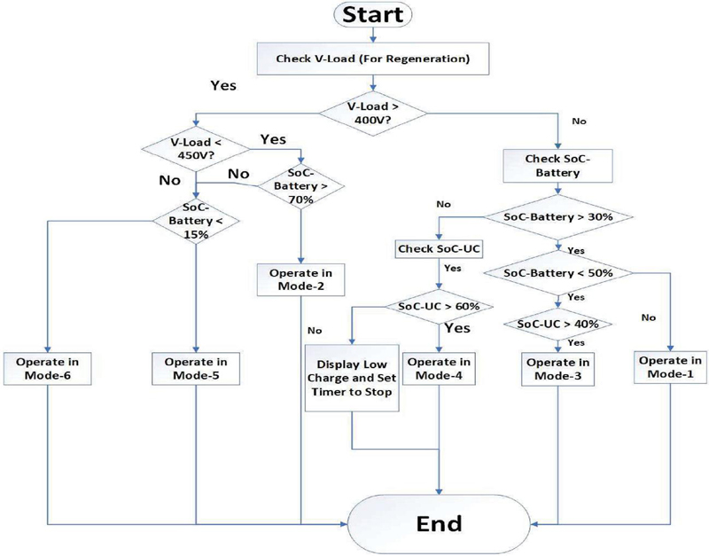
Figure 1 HESS operational modes.
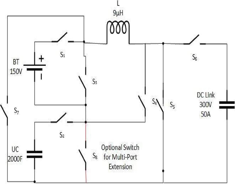
Figure 2 Topology of the proposed hybrid converter.
Our proposed converter has a battery as the main source, an UC as an auxiliary source, several switches (can be any bidirectional switch), a single inductor, and the DC Link, as shown in Figure 1. A capacitor is provided to reduce ripple in the output. Extension of multi ports is possible here by adding additional sources.
Compared to the other topologies, this paper introduces a series of connected sources when multiple sources are working together. Thus, the proposed topology has the advantages of series-connected converters. Based on load requirements, several modes are presented for the working of the converter. The switch S is needed when more than two sources are connected to the inductor. The operation and control of different modes are tabulated below:
Table 2 Different operational modes
| Mode | Operation | Mode Function | Summary |
| 1 | Battery drives the DC link | When only battery is available. | Confirm the energy supply from the battery during standalone operation. |
| 2 | Battery drives the UC | When the battery is available but no load. | Maintains system readiness by balancing energy between the battery and UC. |
| 3 | Battery and UC drive the DC link | When both sources are available. | Combines energy sources to meet high load demands efficiently. |
| 4 | UC drives the DC link | When only UC is available. | Provides temporary power when the battery is not available. |
| 5 | DC link charges the battery | When Regeneration is on and the battery needs to be charged. | Maximizes energy recovery by storing regenerated energy in the battery. |
| 6 | DC link charges the UC | When Regeneration is on and the UC needs to be charged | UC energy storage is promptly restored for upcoming peak power demands. |
Table 2 mentions the operation in different modes. Several more operational modes can be achieved by the proposed configuration. For our purpose, these six operation modes are presented. The switching sequence for the associated mode of operation is given below:
Table 3 Switching sequence in different modes
| Mode | Inductor Charge Cycle (Switch ON) | Inductor Discharge Cycle (Switch ON) |
| 1 | S, S | S, S |
| 2 | S, S | S, S, S |
| 3 | S, S, S | S, S |
| 4 | S, S, S | S, S |
| 5 | S, S | S, S |
| 6 | S, S | S, S, S |
In mode-1 the DC link voltage is greater than the battery voltage and so the battery voltage is boosted to supply the DC link. In the first half-cycle, the inductor L is charged via S1 and S4 and it is then discharged at the DC link via S6 and S7 during the second half-cycle. So, during each of the cycles, the voltage across the inductor can be found by –
V = V in the first half cycle.
V = V in the second half cycle.
The output voltage as such can be given by the following equation from the inductor Volt second balance equation:
| (1) |
Here, T is the time taken for inductor charging when the switches of the first cycle are on, and D is the duty ratio of these switches. T is the time taken for inductor discharging when the switches of the second cycle are on, and D is the duty ratio of these switches, D. T is the switching period. Using the relations of V from the first and second half cycle, we can easily deduce the steady state input and output relation of the proposed converter. It is given by:
| (2) |
In mode 1, V is the battery voltage and V is the voltage at the DC link. The battery drives the DC link by operating the first cycle switches at a duty ratio of over 0.5. Like a conventional DC-DC buck-boost converter, the inductor ripple current in continuous current mode can be given by,
| (3) |
Where, is the ripple current. The minimum capacitance to limit the output voltage ripple is:
| (4) |
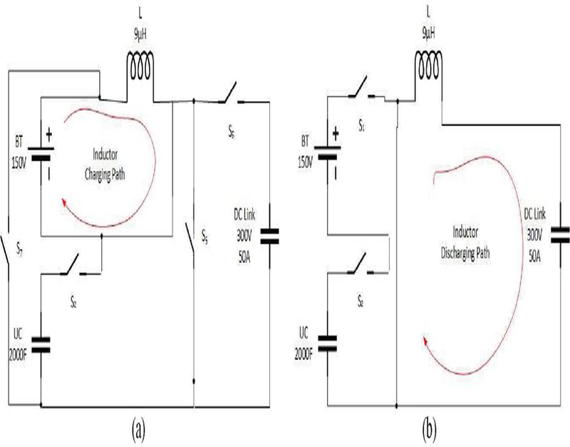
Figure 3 (a) Charge cycle of the inductor in mode-1; (b) Inductor discharge cycle in mode-1.
The operating modes mentioned in Table 2 work similarly. In the first half cycle, the inductor is charged from the source power and then it is discharged at the load in the second half cycle. Equation (2) gives the input-output relation in the steady-state operation of all the modes. In mode 4, the UC drives the DC link in case of unavailability of the battery in the same way as mode 1 operates. In mode 3, both the battery and the UC power the DC link by operating the switches at a duty ratio of over 0.5. Conversely, when there is excess power at the DC link due to some regeneration, it is dissipated at either the battery or the UC by keeping D. This sums up the operation in mode 5 or mode 6. In mode 2, the battery charges the UC by operating D at less than 0.5. This action takes place when there is sufficient charge in the battery and regeneration is taking place but the power is low.
3 Simulation Results and Discussions
The proposed circuit was simulated in MATLAB/SIMULINK 2020a to evaluate its performance under conditions typical for an electric vehicle (EV) load. The desired reference output voltage for the circuit was set at 300 V, a common DC link voltage for EV power systems. The system was designed to deliver 150 kW of output power, simulating the power demand of an electric vehicle under load. This power corresponds to a 500 A load current. A 2000 Farad (F) UC with a rated voltage of 125 V was used in the design to meet the requirements of rapid power delivery. Ultra-capacitors are chosen for their ability to provide bursts of high power for short durations. The 2000 F capacitor was sized to serve a 500 A load during sudden demand surges, essential for applications like electric vehicles that may require a quick boost of power for acceleration. The inductor value in the system was selected as 9 H. The inductor works to smooth out the current ripple in the power flow from the UC and battery, ensuring stable power delivery.
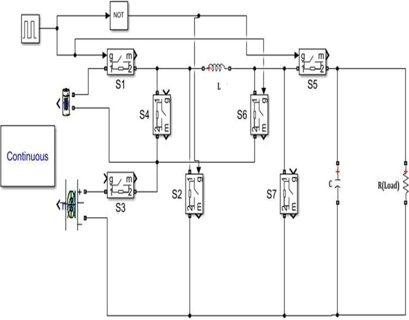
Figure 4 Simulink model used for simulation.
DC Link Modeling for Modes I, III, and IV
• In these modes, the DC link (which helps in stabilizing the voltage across the load) was modeled using a 12.5 mF capacitor and a 0.6 resistor. The capacitor acts as an energy storage component, ensuring a steady voltage at the DC link, while the resistor models the internal losses or resistance in the DC circuit.
Battery Model
• The battery used in the simulation was modeled as a lithium-ion battery sourced from the built-in Simulink power library. Lithium-ion batteries are commonly used in electric vehicles due to their high energy density and long cycle life.
• The battery had a nominal voltage of 150 V and was rated at 2000 Ampere-hours (Ah). This capacity allows the battery to supply 500 A of current continuously for up to 4 hours, making it suitable for powering the EV over a typical driving cycle.
Switching and Control Mechanism
• Switches: The simulation utilized the ideal switch module from the Simulink library. These ideal switches are used to model power electronic components like IGBTs, TRIACs, and MOSFETs which are typically used for controlling the power flow in converters.
• A switching frequency of 5 kHz was chosen for the simulation. The switching frequency determines how often the power electronic switches (like IGBTs or MOSFETs) turn on and off, which in turn controls the power conversion process.
Modes 5 and 6:
• In mode 5 and mode 6, the DC link was modeled as a constant voltage source of 300V. This implies that, in these operating modes, the voltage is regulated externally to ensure that it remains constant, which is essential for stabilizing the system during certain operations.
• The initial OC for the battery was set at 20% in mode-5, simulating a nearly discharged battery scenario. This tests the performance of the system in low-battery conditions, which is critical for understanding the system’s behavior during depletion.
• In mode-2, the initial voltage of the UC was set to 25 V and in mode-6, it was set to 50 V. This lower initial voltage simulates the condition where the UC starts in a partially discharged state and assesses how the UC helps during power surges.
3.1 Control of Duty Cycle (D)
The value of the duty cycle (D) is crucial to control the output voltage of the converter. A proper control mechanism adjusts D to regulate the output voltage and current to the desired level. However, in this particular study, developing a control system was beyond the scope, so pre-determined D values were used to illustrate the converter’s operation in different modes. The values of D (duty cycle in different modes) were chosen to ensure the output voltage met the desired target and were presented in Table 4 to show how the converter behaves under various conditions.
Table 4 Duty cycle values in different operating modes
| Mode | Value of D (%) | D (%) |
| 1 | 65 | 35 |
| 2 | 45 | 55 |
| 3 | 55 | 45 |
| 4 | 75 | 25 |
| 5 | 40 | 60 |
| 6 | 30 | 70 |
Figure 5 depicts the simulation results of mode 1. In mode 1, the load voltage waveform oscillates between 288 V and 293 V with a high frequency. This ripple in the load voltage may be caused by the switching operation of the converter. The slight oscillation indicates that the output voltage is close to the set reference of 300 V, as per the design. The load current also fluctuates within a small range of 479 A to 489 A, which suggests that the load is being served at a relatively constant current, consistent with the target 500 A load. The high-frequency switching action in the converter also causes the ripple in current. The inductor voltage waveform alternates between positive and negative values (approximately 200 V and 300 V). This is a typical behavior for an inductor in a Buck-Boost converter, where it stores energy when the switch is on (positive voltage) and releases energy when the switch is off (negative voltage). The sharp changes indicate high switching frequency, which is typical for power converters. The inductor current has a triangular ripple pattern, oscillating between 250 A and 2500 A. This indicates that the current through the inductor is ramping up and down within each switching cycle. The triangular shape is characteristic of the charging and discharging cycles of an inductor in switching power supplies, where the current ramps up when the switch is closed and ramps down when the switch is open. Load Voltage and Current both are close to their target values (around 300 V and 500 A) but show some ripple due to the switching behavior of the converter. The inductor shows the expected behavior of a converter in continuous conduction mode (CCM), with the inductor voltage switching between positive and negative, and the inductor current oscillating with a triangular waveform. The presence of ripples in the waveforms is normal for power electronics circuits, especially those operating with high-frequency switching. The ripple values are within acceptable limits, indicating that the system is operating as expected. The battery voltage starts at around 175 V and gradually decreases over time, indicating a steady decline in the battery’s voltage as it is discharged. The overall trend shows the typical behavior of a battery discharging under load. The voltage oscillates between approximately 160 V and 162.5 V, reflecting this repetitive load pattern. The current plot shows a cyclic pattern, with spikes going up to 2500 A and dropping to 0 A. This indicates a steady current drawn from the battery over the period. The state of charge decreases gradually, starting at 100% and moving downward, as the battery depletes. This linear decrease suggests that the load and discharge rates are relatively steady.
Figure 6 depicts the simulation results of mode 2. In mode 2, the UC voltage increases steadily from 25 V to 125 V over a span of 200 seconds, which corresponds to a rise in the SoC from 20% to 90%. Once it reaches a steady state, the UC voltage fluctuates between 114 V and 134 V. Initially, the charging current is very high at 10 kA, but it gradually decreases and stabilizes at 2500 A. The inductor’s voltage also exhibits notable behavior, peaking at 155 V and dropping as low as -140 V. The inductor current increases linearly from 800 A to 2400 A and then falls, completing a full charge-discharge cycle. Interestingly, the initial inductor current is quite large, exceeding 10 kA, which is attributed to the abrupt operation of switches. The battery exhibits similar characteristics to those observed in mode 1, where its voltage gradually decreases from 175 V to 160 V, and the current declines from 10 kA to 2 kA. The SoC of the battery steadily decreases as well, indicating a consistent discharge rate.
Figure 7 depicts the simulation results of mode 3. In mode 3, both the battery and the UC are supplying power to the load, which occurs when there is an increase in load current. The load and inductor currents follow a pattern similar to that seen in mode 1. The load voltage, in a steady state, oscillates between 318 V and 325 V. The load current initially increases from 530 A to 541 A, then drops over a full cycle. The voltage across the inductor alternates between 310 V and 290 V, while the inductor current fluctuates between 400 A and 2700 A. In this mode, the battery voltage stabilizes at 165.5 V, and its current surges from 0 to 2800 A. The UC voltage reaches a steady value of 110 V, and the UC current follows a similar pattern to that of the battery.
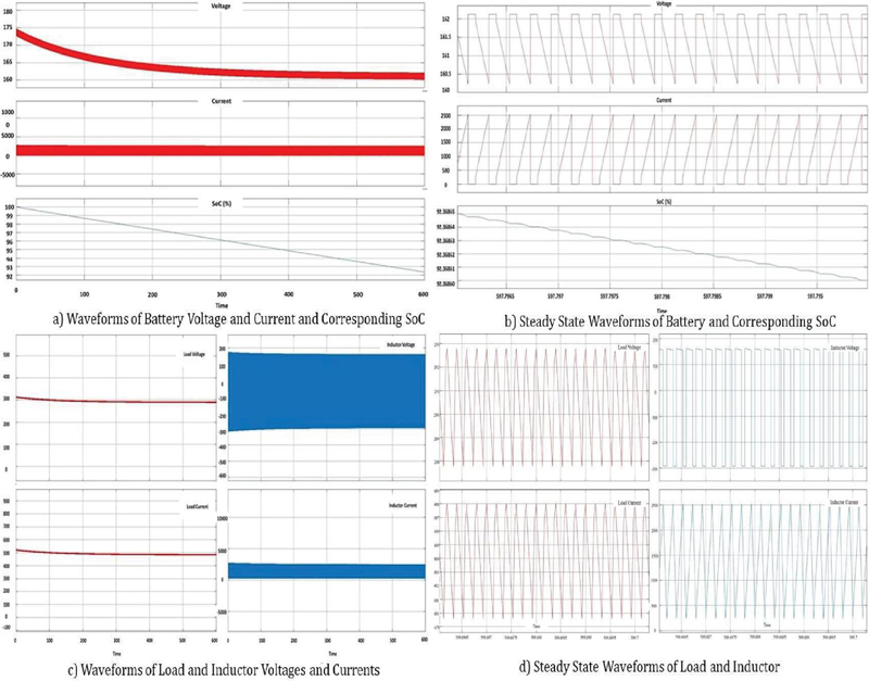
Figure 5 Battery, load, inductor voltage, current, and SoC analysis in mode-1.
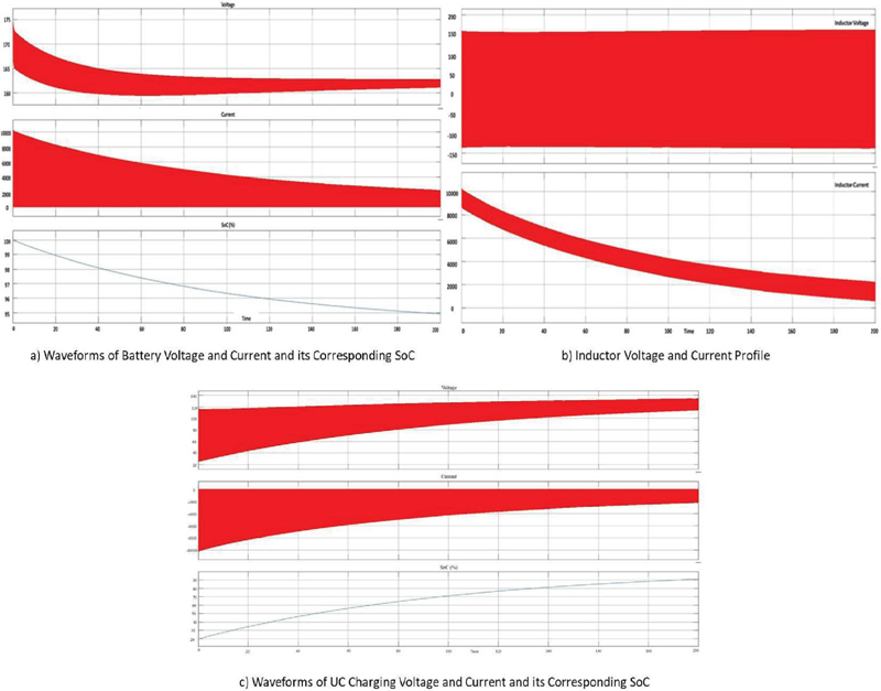
Figure 6 Battery, inductor and UC voltages, currents, and the corresponding SoC of battery and UC in mode-2.
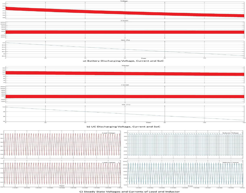
Figure 7 Battery and UC discharging characteristics with inductor and load profile in mode 3.
In mode 4, when the battery is unavailable, the UC alone powers the load. The steady-state waveforms of both the load and the inductor resemble those observed in mode 1, albeit with reduced values. The UC voltage and SoC settle at 30 V and 30%, respectively, and the output voltage falls below 100 V (Figure 8). Despite this drop, the UC provides a driving current of 335 A to the load. Modes 5 and 6 deal with the dissipation of power generated during regenerative processes. In mode 5, the battery is charged with a current of 2.2 kA, and its SoC increases linearly from 20% to over 90% within 400 seconds. During this time, the battery voltage rises from 160 V to 214 V. In mode 6, the inductor current oscillates between 1100 A and 900 A, and the UC is fully charged from an SoC of 40% to 100% over 400 seconds. Proper control mechanisms of the duty cycles of every switch will enable better voltage and current regulation at the output. UC charging characteristics in Mode 5 and the battery charging characteristics in Mode 6, as depicted in Figure 9.
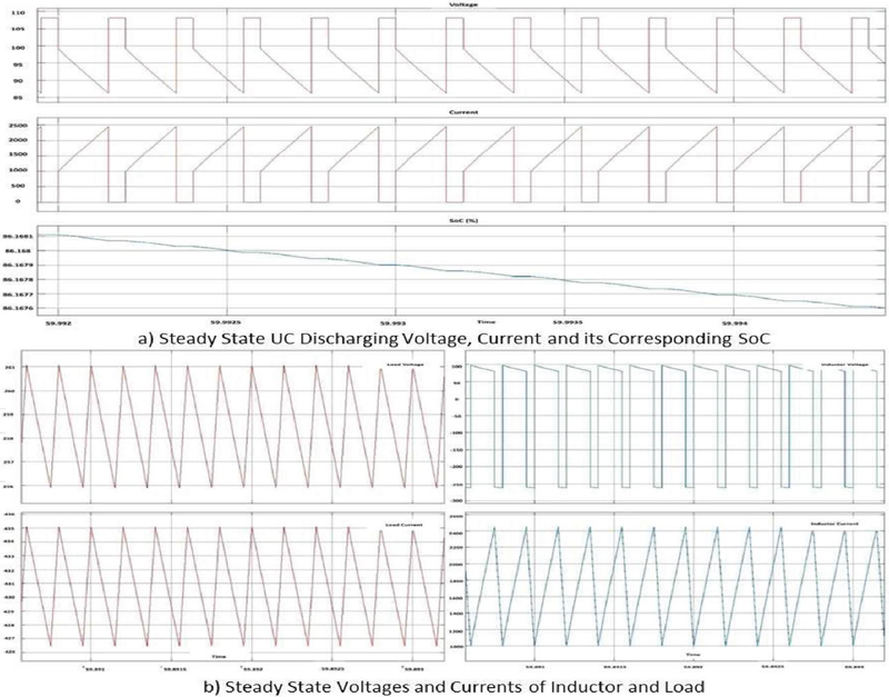
Figure 8 UC discharging voltage & current & load and inductor profile in mode 4.
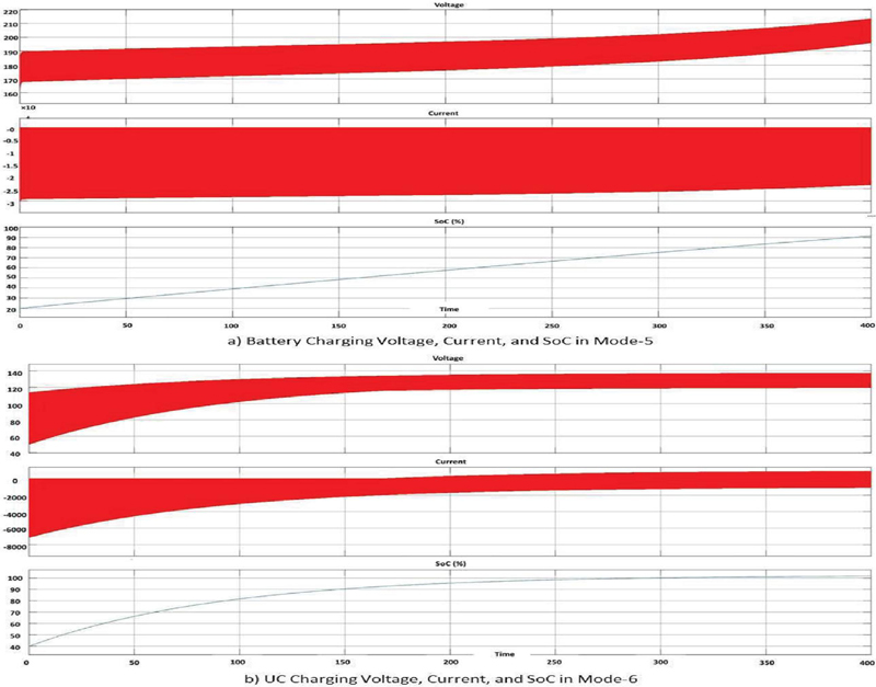
Figure 9 Battery and UC charging characteristics in mode 5 and mode 6.
3.2 Discussion
Modes 5 and 6 focus on the dissipation of power generated during regenerative processes. In Mode 5, the battery has been charged with a current of 22 kA, and its SoC increased linearly from 20% to over 90% within 400 seconds. Simultaneously, the battery voltage increased from 160 V to 214 V. In Mode 6, the inductor current oscillated between 1100 A and 900 A, while the UC charged fully, with its SoC rising from 40% to 100% over 400 seconds. Appropriate control mechanisms for the duty cycles of each switch are crucial for achieving better voltage and current regulation at the output.
The different modes of operation reveal critical insights into the performance and behavior of the power converter system, predominantly in terms of voltage, current, and SoC dynamics across the battery and UC. Each mode demonstrated specific characteristics that are crucial for understanding how the system responds to varying load demands, switching frequencies, and energy storage mechanisms. In Mode 1, the oscillations in both load voltage and current, though minimal, indicate that the system is operating close to its design setpoints of 300 V and 500 A, respectively. These fluctuations are expected in systems with high-frequency switching, such as converters using pulse-width modulation (PWM) techniques. The ripple in voltage and current is within acceptable limits, suggesting effective regulation despite the switching-induced perturbations. The inductor’s triangular current waveform is a hallmark of continuous conduction mode (CCM), where energy is continuously transferred to the load, preventing discontinuities in current flow. The inductor voltage alternating between positive and negative values further validates that the system is effectively managing energy storage and release during each switching cycle. These results suggested that the converter performances are adequate as expected, and maintained stable operation while providing consistent power to the load. The battery’s gradual voltage decreases and linear SoC reduction reflect a typical discharging behavior under load, reinforcing the system’s ability to supply power over time.
In Mode 2, the linear rise in UC voltage and SoC during the charging phase highlights the system’s capacity for energy storage. The high initial charging current, which tapers off as the UC approaches a full charge, indicates the rapid energy absorption capability of ultracapacitors, particularly when they are in a low-charge state. The stabilization of current and voltage at higher SoC levels underscores the system’s ability to manage charging efficiently, preventing overcharging and ensuring the longevity of the storage component. The observed behavior of the inductor, with its voltage and current responding in tandem to the charging and discharging cycles, aligns with expectations for energy transfer between the UC and the load. The battery’s performance in this mode mirrors that of Mode 1, with a consistent decline in voltage and SoC, further confirming the steady discharge characteristics under sustained operation.
Mode 3 introduces a more complex scenario where both the battery and the UC supply power to the load. The ability of the system to dynamically share the load between the two energy storage components is evidenced by the fluctuations in current and voltage across both the battery and UC. The load voltage remains relatively stable, oscillating within a narrow range, while the load current experiences minor fluctuations. This indicates that the system is effectively distributing power based on the demand, ensuring that neither the battery nor the UC is overburdened. The behavior of the inductor, with its voltage alternating between negative and positive values, and the current oscillating between 400 A and 2700 A, suggests that energy is being efficiently transferred between the UC and load. The gradual decrease in SoC for both the battery and UC reflects a slow energy depletion, indicating a balanced discharge rate that supports sustained power delivery.
In Mode 4, where the UC alone powers the load, the system demonstrates its ability to rely solely on the UC when the battery is unavailable. The triangular sawtooth waveform in the UC voltage and current is a clear indication of the charging and discharging cycles typical of switching converters. The slow decline in both voltage and SoC over time indicates a gradual depletion of energy from the UC, which is expected when the load is entirely supported by the UC. The load voltage and current oscillations remain within acceptable bounds, suggesting that the UC can maintain stable power output despite the absence of the battery. The inductor’s sawtooth waveform further highlights the continuous energy transfer and the gradual decline in current indicates a smooth discharging process.
Modes 5 and 6 focus on regenerative processes, wherein energy is fed back into the battery and UC for storage. In Mode 5, the charging of the battery with a current of 22 kA leads to a linear increase in SoC, with the battery voltage rising from 160 V to 214 V. This steady increase in both voltage and SoC underscores the system’s efficiency in managing regenerative energy. In Mode 6, the inductor current oscillates between 1100 A and 900 A, highlighting the dynamic nature of energy transfer during regenerative braking or similar processes. The UC’s SoC increases from 40% to 100% within 400 seconds, confirming that the system can fully charge the UC under regenerative conditions. Table 5 provides the summary of the output ripples observed in the various operational modes.
Table 5 Inductor and output ripple quantity at steady state
| Mode | 1 | 2 | 3 | 4 | 5 | 6 |
| Output Voltage Ripple (%) | 1.38 | 16 | 1.55 | 1.93 | 7.32 | 11.54 |
Overall, the ripple observed in the voltage and current waveforms across all modes is consistent with typical behavior in power electronic systems that utilize high-frequency switching. While the ripple introduces small fluctuations, the system’s performance remains well within design specifications, ensuring stable operation and efficient energy transfer. These results demonstrate the system’s robustness in handling different load conditions, switching dynamics, and energy storage states, making it suitable for applications where reliable power delivery and energy efficiency are paramount. The gradual declines in battery voltage and SoC, coupled with the stable operation of the UC, highlight the complementary roles of these energy storage components. The UC provides fast response and high power density, while the battery ensures a long-term energy supply. Together, they form a resilient energy management system capable of adapting to various operational demands, whether in steady-state operation, high-demand situations, or during regenerative braking. This comprehensive analysis of each mode’s behavior provides valuable insights into the design and functionality of power converters, demonstrating how such systems can be optimized for reliable and efficient energy management across a wide range of operating conditions.
4 Conclusions
This study proposes a HESS that integrates a battery and an UC, leveraging the strengths of both energy storage technologies. The battery, known for its high energy density, provides a long-term energy supply, while the ultracapacitor, with its high power density, handles rapid charge and discharge cycles. This combination allows for enhanced performance in energy storage and delivery, addressing both energy capacity and quick power response needs. The hybrid system is coupled with a versatile power converter that can operate in three different modes: buck, buck-boost, or boost mode, depending on the switching control strategy employed. The converter’s operation in buck mode allows for voltage step-down, while in boost mode, it enables voltage step-up. In buck-boost mode, it provides both functionalities, depending on the power requirements at a given moment. The converter’s bidirectional power flow capability ensures that power can be efficiently transferred between the battery, ultracapacitor, and load, making it ideal for systems that require flexible energy management. Simulation results demonstrate that the converter maintains a steady DC link voltage of 300 V under varying load conditions, with load voltage fluctuations confined to 5 V, ensuring stable performance. The system satisfies the requirements common to electric car applications by supporting a high load of 150 kW and a current of up to 500 A. While the battery shows steady discharge behavior and maintains a steady power output, the ultra-capacitor charges quickly, reaching 90% State of Charge (SoC) in about 200 seconds. The effectiveness of energy recovery is further demonstrated by the battery’s SoC rising from 20% to over 90% in 400 seconds during regenerative operations. Likewise, the ultra-capacitor showcases its rapid reaction capabilities by reaching full charge (40% to 100% SoC) in the same amount of time. The suggested system’s applicability for applications needing dependable and dynamic energy management, such as renewable energy systems and electric cars, is confirmed by these performance metrics.
Furthermore, it can be used in distributed energy resources (DERs), smart grids, and microgrids, where different energy sources, such as solar panels, wind turbines, or fuel cells, need to be integrated and managed. The hybrid storage system can also benefit battery management systems, ensuring optimal performance and longevity by distributing power delivery between the battery and the ultracapacitor based on demand. Future research in this area may focus on developing an advanced control scheme to optimize the operation of the switches within the converter. This would ensure proper regulation of voltage levels and charging currents, enhancing the overall efficiency and reliability of the system. A well-designed control algorithm could improve the dynamic response, reduce energy losses, and ensure stable power delivery across various operating conditions, further expanding the applicability of the hybrid system in real-world energy management scenarios.
Author Contributions
Conceptualization, methodology, software, investigation, visualization, and validation, M.M.; and T.A.; formal analysis,; data curation, K.Z.M.; A.R.; M.K.B.; and M.N-E-A; writing – original draft preparation, M.M.; and T.A.; writing – review and editing: M.N-E-A.; All authors have read and agreed to the published version of the manuscript.
Acknowledgment
The authors also would like to acknowledge the Department of Electrical & Electronic Engineering, Bangladesh University of Engineering & Technology, Bangladesh, and Universiti Tenaga Nasional, Malaysia.
Declarations
Funding
Not Applicable.
Data Availability Statement
All data generated or analyzed during this study are included in this published article.
Institutional Review Board Statement
Not applicable.
Informed Consent Statement
Not applicable.
Conflicts of Interest
The authors declare no conflict of interest.
References
[1] A. Affam, Y. M. Buswig, A.-K. B. H. Othman, N. B. Julai, and O. Qays, “A review of multiple input dc-dc converter topologies linked with hybrid electric vehicles and renewable energy systems,” Renewable and Sustainable Energy Reviews, vol. 135, p. 110186, Jan. 2021.
[2] W. Jiang and B. Fahimi, “Multi-port power electric interface for renewable energy sources,” in 2009 Twenty-Fourth Annual IEEE Applied Power Electronics Conference and Exposition, Feb. 2009.
[3] Y.-M. Chen, A. Q. Huang, and X. Yu, “A high step-up three-port dc-dc converter for stand-alone pv/battery power systems,” IEEE Transactions on Power Electronics, vol. 28, pp. 5049–5062, Nov. 2013.
[4] Hui, A. Bakhshai, and P. K. Jain, “A hybrid wind-solar energy system: A new rectifier stage topology,” in 2010 Twenty-Fifth Annual IEEE Applied Power Electronics Conference and Exposition (APEC), Feb. 2010.
[5] L. Solero, A. Lidozzi, and J. A. Pomilio, “Design of multiple-input power converter for hybrid vehicles,” IEEE Transactions on Power Electronics, vol. 20, pp. 1007–1016, Sep. 2005.
[6] M. Marchesoni and C. Vacca, “New dc-dc converter for energy storage system interfacing in fuel cell hybrid electric vehicles,” IEEE Transactions on Power Electronics, vol. 22, pp. 301–308, Jan. 2007.
[7] A. Hintz, U. R. Prasanna, and K. Rajashekara, “Novel modular multiple input bidirectional dc-dc power converter (MIPC) for HEV/FCV application,” IEEE Transactions on Industrial Electronics, vol. 62, pp. 3163–3172, May. 2015.
[8] D. Liu and H. Li, “A novel multiple-input ZVS bidirectional dc-dc converter,” in Proceedings of the IEEE 32nd Annual Conference on Industrial Electronics Society, pp. 579–584, Nov. 2005.
[9] X. Jun, Z. Xing, Z. Chong-wei, and L. Sheng-yong, “A novel three-port bi-directional dc-dc converter,” in The 2nd International Symposium on Power Electronics for Distributed Generation Systems, Jun. 2010.
[10] X. Sun, G. Pei, S. Yao, and Z. Chen, “A novel multi-port dc/dc converter with bi-directional storage unit,” in Proceedings of The 7th International Power Electronics and Motion Control Conference, Jun. 2012.
[11] H. Davazdah-emami, E. Farjah, T. Ghanbari, and N. Tashakor, “A dc-dc multiport converter with bidirectional energy exchange capability,” in 2016 24th Iranian Conference on Electrical Engineering (ICEE), May. 2016.
[12] R. Faraji and H. Farzanehfard, “Fully soft-switched multiport dc-dc converter with high integration,” IEEE Transactions on Power Electronics, vol. 36, pp. 1901–1908, Feb. 2021.
[13] S. Alomari and I. Smadi, “Modeling and control of multi-port dc/dc converter,” in 2019 IEEE 28th International Symposium on Industrial Electronics (ISIE), Jun. 2019.
[14] K. Suresh, C. Bharatiraja, N. Chellammal, M. Tariq, R. K. Chakrabortty, M. J. Ryan, and B. Alamri, “A multifunctional non-isolated dual input-dual output converter for electric vehicle applications,” IEEE Access, vol. 9, pp. 64445–64460, 2021, doi: 10.1109/ACCESS.2021.3074581.
[15] P. Mohseni, S. H. Hosseini, M. Sabahi, T. Jalilzadeh, and M. Maalandish, “A new high step-up multi-input multi-output DC–DC converter,” IEEE Transactions on Industrial Electronics, vol. 66, no. 7, pp. 5197–5208, 2019, doi: 10.1109/TIE.2018.2868281.
[16] S. Athikkal, G. G. Kumar, K. Sundaramoorthy, and A. Sankar, “A non-isolated bridge-type DC–DC converter for hybrid energy source integration,” IEEE Transactions on Industry Applications, vol. 55, no. 4, pp. 4033–4043, 2019, doi: 10.1109/TIA.2019.2914624.
[17] S. Vahid, P. Zolfi, J. Land, and A. EL-Refaie, “An isolated step-down multi-port DC-DC power converter for electric refrigerated vehicles auxiliary power unit system,” in Proc. 2022 IEEE Applied Power Electronics Conference and Exposition (APEC), 2022, pp. 1133-1140, doi: 10.1109/APEC43599.2022.9773710.
[18] T. Jalilzadeh, N. Rostami, E. Babaei, and S. H. Hosseini, “Multiport DC–DC converter with step-up capability and reduced voltage stress on switches/diodes,” IEEE Transactions on Power Electronics, vol. 35, no. 11, pp. 11902–11915, 2020, doi: 10.1109/TPEL.2020.2982454.
[19] S. Kim, S. Jo, C.-H. Jo, G. Li, and D.-H. Kim, “Single inductor-multi input single output buck-boost converter for PV system,” in Proc. 2024 IEEE 10th International Power Electronics and Motion Control Conference (IPEMC2024-ECCE Asia), 2024, pp. 1481–1485, doi: 10.1109/IPEMC-ECCEAsia60879.2024.10567895.
[20] Z. Saadatizadeh, P. C. Heris, and H. A. Mantooth, “Modular expandable multi-input multioutput (MIMO) high step-up transformerless DC–DC converter,” IEEE Access, vol. 10, pp. 53124–53142, 2022, doi: 10.1109/ACCESS.2022.3175876.
[21] R. Faraji, L. Ding, M. Esteki, N. Mazloum, and S. A. Khajehoddin, “Soft-switched single inductor single stage multiport bidirectional power converter for hybrid energy systems,” IEEE Transactions on Power Electronics, vol. 36, no. 10, pp. 11298–11315, 2021, doi: 10.1109/TPEL.2021.3074378.
[22] S. R. Khasim, C. Dhanamjayulu, and S. M. Muyeen, “A single inductor multi-port power converter for electric vehicle applications,” IEEE Access, vol. 11, pp. 3367–3385, 2023, doi: 10.1109/ACCESS.2023.3234105.
[23] K. Alremeithi and W. Sealy, “Scalable multi input multi output (MIMO) DC-DC buck converter,” in Proc. 2024 IEEE International Conference on Electro Information Technology (eIT), 2024, pp. 1–7, doi: 10.1109/eIT60633.2024.10609842.
[24] N. Yadav and A. Chub, “Multiport current fed push/pull partial power converter for battery integration in DC microgrid,” in Proc. 2024 IEEE 18th International Conference on Compatibility, Power Electronics and Power Engineering (CPE-POWERENG), 2024, pp. 1–6, doi: 10.1109/CPE-POWERENG60842.2024.10604406.
Biographies

Monowar Mahmud completed his graduation from Bangladesh University of Engineering & Technology in Electrical and Electronic Engineering in 2017. After that, he worked in a renowned public electricity distribution company as an assistant engineer for 4 years. He is currently pursuing his master’s degree at Universiti Tenaga Nasional, Malaysia alongside working in the photonics laboratory as a graduate research assistant at the same institution.

Tarek Abedin pursued his bachelor’s degree in electrical and electronics engineering from American International University, Bangladesh in 2016. He is currently continuing his PhD at Universiti Tenaga Nasional (UNITEN), Malaysia on Hydrogen fuel cells and working as a research assistant. Previous projects he has done are “Voice Controlled Humanoid Surveillance Robot”, and HVDC Dynamic Modelling for Power System Stability Assessment, and have done a plethora of Automation Based projects. His research interests include Hydrogen fuel cells, machine learning robotics, automation technology, and control-based maintenance technology.

Kazi Zehad Mostofa is a graduate student specializing in Electrical and Computer Engineering at Clarkson University, Potsdam, NY, with a focus on Power and Renewable Energy Engineering. He earned his bachelor’s degree in electrical engineering from Universiti Malaya, Malaysia in 2022, where he conducted innovative research in renewable energy, supported by the Universiti Malaya Undergraduate Research Fellowship Grant for his final year project on sustainable energy systems. Before pursuing his master’s, Mr. Mostofa served as a Research Assistant at the Next Generation Energy Lab, University of Malaya, where he designed hybrid PV systems for school buildings achieving up to 78% energy self-sufficiency and significant carbon emission reductions. He also developed energy optimization models using HOMER Pro, Python, MATLAB and contributed to actionable insights for regulatory compliance and sustainability initiatives. Additionally, as a Product Research and Development Engineer at Penco Electronics, he implemented IoT-based real-time energy monitoring systems with 92% efficiency and improved product reliability through hardware and software troubleshooting.
His teaching and research expertise includes topics such as renewable energy systems, microgrid design, energy management, and IoT applications in energy monitoring. His projects range from EV charging station performance optimization to microgrid economic dispatch modeling. His publications include works on all-PV blended system design, net-zero building energy design, self-sustainable cold storage design, and microgrid optimization. He has presented his research findings at several prestigious international conferences and symposiums.

Atiqur Rahman is an Assistant Professor and Head of the Computer Science and Engineering Department at Chittagong Independent University (CIU), Bangladesh. He earned his MPhil by Research from the Department of Electronic Systems Engineering at the Malaysia-Japan International Institute of Technology, Universiti Teknologi Malaysia 2020, with a thesis focused on developing an energy-efficient routing protocol for hierarchical cognitive radio ad hoc networks. Prior to that, he completed a combined B.Sc. and M.Sc. in Engineering at Kharkov National University of Radio Electronics in 1999, where he received “excellent” marks for his thesis on the development of network composition based on fast Ethernet technology. His teaching expertise includes courses such as Wireless Communication, Data Communication, Digital Logic Design, and Discrete Mathematics. Besides his teaching responsibilities, Mr. Rahman is actively involved in research, with interests in wireless communication, and smart energy systems. His publications include works on automated smart car parking systems employing Internet of Things technology and mobile edge computing for IoT security and privacy issues.

Mohammad Khairul Basher is a researcher specializing in materials science and renewable energy technologies. He earned his PhD from Edith Cowan University (ECU) in Perth, Australia, where his research focused on developing aesthetically appealing building-integrated photovoltaic (BIPV) systems for net-zero energy buildings. Prior to his doctoral studies, Dr. Basher completed a Master of Philosophy (M.Phil) in Materials Science at the Bangladesh University of Engineering and Technology (BUET) from 2011 to 2016. He also holds a Master of Science (M.S) and a Bachelor of Science (B.Sc) in Applied Physics, Electronics & Communication Engineering from the University of Chittagong, completed between 2002 and 2008.
Dr. Basher served as a Senior Scientific Officer at the Bangladesh Atomic Energy Commission, contributing to various research projects in the field. His research interests include colored photovoltaics, agrophotovoltaics, sustainable energy harvesting systems, and net-zero energy buildings.

Mohammad Nur-E-Alam received Ph.D. from Edith Cowan University, Australia. He is an active research professional in the field of Materials Science and Engineering. His work is of high quality, and international standard and represents true eminence in his research field. He is an experienced researcher with a demonstrated history of working in the higher education industry. He has co-authored several high-impact research articles published in international peer-reviewed journals. His research areas and interests are Magneto-photonic/plasmonic crystals, thin film materials, coatings, and applications, Micro/Nanofabrication processes, Optical microstructures, smart energy harvesting systems, hybrid energy systems, and renewable energy.
Journal of Graphic Era University, Vol. 13_1, 155–182.
doi: 10.13052/jgeu0975-1416.1318
© 2025 River Publishers